Non-Conductive Coolants: Why Ultrasonic Flowmeters Are the Inevitable Choice
1. Introduction: Non-conductive Coolant for Liquid Cooling
When the power consumption of a single AI training chip exceeds 1000 W and the heat density of a GPU server rack surpasses 100 kW, traditional air cooling — with a heat transfer coefficient only 1/25 that of liquid — is no longer an option but a bottleneck. Liquid cooling has rapidly shifted from an “optional solution” to a “mandatory solution.”
However, liquid cooling is not a single technology. A fundamental choice lies at the root of every liquid cooling architecture: Must the coolant be conductive? The answer determines system architecture, safety boundaries, and maintenance logic — and ultimately decides which flow measurement technology should be used.
This report analyzes the topic from three perspectives:
1.Why non-conductive coolants are adopted — technical drivers and irreplaceability
2.Which liquid cooling scenarios require non-conductive coolants — from data centers to power battery thermal management
3.Why ultrasonic flowmeters hold a fundamental advantage in these scenarios — necessity at the measurement principle level
2. Why Use Non-Conductive Coolants?
2.1 Core Conflict: Heat Transfer Efficiency vs. Electrical Safety
The fundamental advantage of liquid cooling lies in the high specific heat capacity and thermal conductivity of liquids. However, the objects being cooled are live electronic components. If the coolant is conductive:
1.Any leakage onto a PCB can cause immediate short circuits and burn chips or motherboards.
2.Micro-leakage inside cold plates can lead to creepage on circuit boards, resulting in catastrophic failure.
3.Multiple layers of physical isolation must be maintained between the fluid loop and electronic components, increasing thermal resistance.
The adoption of non-conductive coolants (dielectric fluids) fundamentally upgrades “leakage tolerance” from “zero tolerance” to “acceptable risk.” This is not an incremental improvement but an architectural paradigm shift — it enables direct liquid contact with electronic components.
2.2 Key Performance Indicators of Non-Conductive Coolants
According to the Immersion Liquid Cooling Coolant Selection Requirements (TCI Group Standard), non-conductive coolants must meet the following criteria:
|
Category
|
Key Parameter
|
Typical Requirement
|
Technical Significance
|
|
Electrical Insulation
|
Dielectric Strength
|
>40 kV (Data Center)
|
Prevents breakdown under high voltage
|
|
Heat Transfer
|
Thermal Conductivity
|
≥0.18 W/m·K (Data Center)<br>≥0.2 W/m·K (Ultra-fast Charging)
|
Determines maximum cooling efficiency
|
|
Fluid Properties
|
Kinematic Viscosity
|
≤10 mm²/s (Ultra-fast Charging)
|
Affects pump power and circulation efficiency
|
|
Thermal Stability
|
Flash Point
|
>200°C (Industrial)
|
Safety boundary for high-temperature operation
|
|
Material Compatibility
|
Metal Weight Loss
|
≤0.5% after 6 months immersion
|
Long-term operational reliability
|
|
Environmental
|
GWP Value
|
Continuously tightening
|
Global emission compliance
|
2.3 Technical Positioning of Three Major Non-Conductive Coolant Categories
|
Dimension
|
Hydrocarbon / Organosilicon
|
Fluorocarbon
|
Mineral Oil
|
|
Representative Products
|
Synthetic hydrocarbon oil (CXCH-220), Silicone oil
|
Fluorinated liquids (FC-3283)
|
White oil, Transformer oil
|
|
Market Positioning
|
Dominant in single-phase market
|
Dominant in two-phase market
|
Low-end transitional solution
|
|
Core Advantages
|
PUE ≤1.08, controllable cost, biodegradable
|
Non-flammable, high latent heat of vaporization
|
Lowest cost
|
|
Core Risks
|
Flammable
|
High GWP, environmental pressure
|
Poor oxidation resistance, low flash point
|
|
Development Trend
|
Current mainstream, continuous growth
|
3M announced in 2022 to exit all PFAS manufacturing by end of 2025 (completed)
|
Gradual phase-out
|
Technology Trend Assessment: Hydrocarbon and organosilicon fluids are currently the mainstream choice for single-phase immersion cooling. Fluorocarbon fluids face global restrictions due to PFAS environmental regulations. The development of new environmentally friendly dielectric fluids has become an industry imperative.
3. Liquid Cooling Scenarios That Require Non-Conductive Coolants
Is there any possibility of the coolant coming into direct contact with live components?
If the answer is yes — whether by design or due to leakage risk — non-conductive coolant is not an optimization option but a safety necessity.
3.2 Five Core Application Scenarios
Scenario 1: Data Center Immersion Liquid Cooling (Single-Phase / Two-Phase)
When rack power density exceeds 50 kW, cold-plate liquid cooling reaches its thermal resistance limit. Immersion cooling submerges entire servers in dielectric fluid, eliminating the thermal interface material (TIM) layer between the chip and cold plate.
Rigid Requirement: Servers operate under power with motherboards, CPUs, and memory fully immersed. Dielectric strength >40 kV is a non-negotiable safety threshold.
Scenario 2: Immersion Cooling for Electric Vehicle Power Batteries
Lithium battery thermal runaway occurs at only 120–150°C. Under fast-charging conditions, a single cell can generate tens of watts of heat. Immersion cooling is currently the only technology capable of achieving cell-level temperature uniformity (temperature difference <3°C).
Rigid Requirement: Battery module voltage ranges from 400–800 V. The coolant must provide both electrical insulation and flame retardancy.
Scenario 3: Ultra-Fast Charging Station Power Module Cooling
600 kW ultra-fast chargers have extremely high heat flux in power modules. Traditional air cooling is insufficient. Power devices operate in high-voltage environments, requiring coolants with high dielectric strength and low flash points.
Scenario 4: Energy Storage Station Thermal Management
Fire safety is the core constraint for large-scale energy storage stations. Non-conductive coolants serve dual purposes as both heat transfer media and flame-retardant layers.
Scenario 5: Industrial Automation
Industrial lasers have extremely high power density. Coolants must maintain dielectric properties at temperatures above 300°C with flash points exceeding 200°C.
3.3 Key Comparison: Conductive vs. Non-Conductive Coolants
|
Dimension
|
Conductive Coolant (Water/Glycol)
|
Non-Conductive Coolant (Dielectric Fluid)
|
|
Typical Applications
|
Cold-plate liquid cooling, CDU secondary loop
|
Immersion liquid cooling, battery immersion cooling
|
|
Relationship with Electronics
|
Must maintain physical isolation
|
Direct contact possible
|
|
Consequence of Leakage
|
Short-circuit risk, catastrophic failure
|
Insulation safety, controllable impact
|
|
Thermal Resistance Layers
|
Chip → TIM → Cold plate → Coolant (4 layers)
|
Chip → Coolant (1 layer)
|
|
Conductivity
|
50–500 μS/cm
|
<0.1 μS/cm
|
|
System Complexity
|
High (strict sealing required)
|
Low (high leakage tolerance)
|
4. Why Ultrasonic Flowmeters Hold a Structural Advantage in Non-Conductive Coolant Applications
4.1 The Critical Need for Coolant Flow Rate Measurement
In liquid cooling systems, flow rate is not just reference data — it is a control variable. Accurate flow monitoring enables dynamic regulation, early detection of leaks or blockages, and balanced flow distribution across multiple branches.
4.2 Limitations of Mainstream Flow Measurement Technologies with Non-Conductive Fluids
Electromagnetic Flowmeters: Technical Failure
Electromagnetic flowmeters require a minimum fluid conductivity of 5–20 μS/cm. Non-conductive coolants (typically <0.01 μS/cm) fall far below this threshold, making electromagnetic flowmeters physically incompatible.
Coriolis Flowmeters: Usable but Expensive
Coriolis flowmeters can measure non-conductive fluids but introduce significant pressure drop, are vibration-sensitive, and are 3–5 times more expensive than ultrasonic solutions.
Turbine / Rotameter Flowmeters: Wear and Reliability Risks
These contain moving parts that are prone to wear and blockage, especially in 7×24-hour data center environments.
4.3 Ultrasonic Flowmeters: The Future-Proof Choice
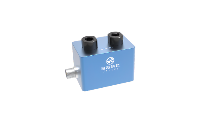
XY-TEK TPD series ultrasonic flow sensors / flow meters operate on the ultrasonic transit-time principle, which is completely independent of fluid conductivity. This is the root of their technical advantage.
Five Core Advantages:
-
Native Compatibility with dielectric fluids (synthetic hydrocarbons, fluorinated liquids, mineral oils).
-
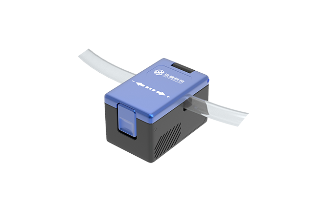
Non-Intrusive Measurement (Clamp-on type) — 0 leakage risk and no pipe cutting.
-
0 Pressure Loss — no impact on system pumping efficiency.
-
No Moving Parts — virtually maintenance-free in continuous operation.
-
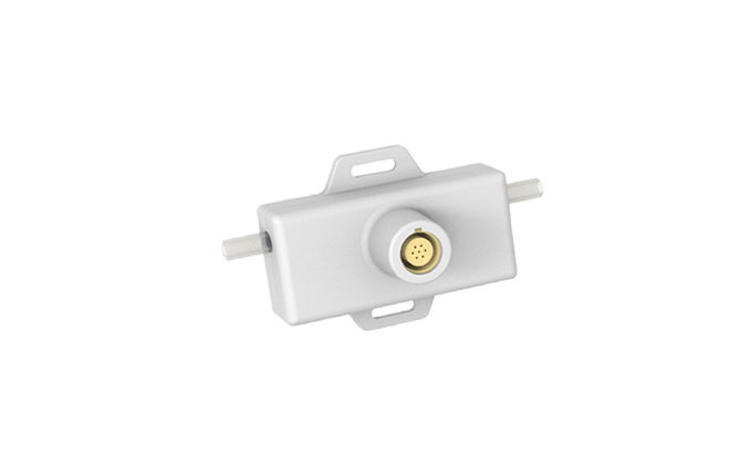
Wide Pipe Size Coverage — from DN6 to DN50, meeting flow ranges from 1–2 L/min (single GPU) to 100–300 L/min (high-density racks).
4.4 Summary Comparison of Flow Sensor / Flow Meter Technologies for Non-Conductive Coolants
|
Evaluation Dimension
|
Electromagnetic
|
Coriolis
|
Turbine
|
Ultrasonic
|
|
Non-Conductive Fluid Compatibility
|
Not usable
|
Usable
|
Usable
|
Usable
|
|
Pressure Loss
|
Low
|
High
|
Medium
|
Zero
|
|
Moving Parts
|
None
|
None (vibrating tube)
|
Yes
|
None
|
|
Small Tubing Size (DN6–25)
|
Usable
|
Very Expensive
|
Usable but wears
|
Excellent
|
|
Maintenance Requirement
|
Low
|
Low
|
High
|
Very Low
|
|
Leakage Risk
|
Present
|
Present
|
Present
|
None (Clamp-on) / Very Low (In-line)
|
|
Overall Rating
|
Not usable
|
Usable but not optimal
|
Usable
|
Ideal Choice
|
5. The Optimal Combination: Non-Conductive Coolant + Ultrasonic Flowmeter
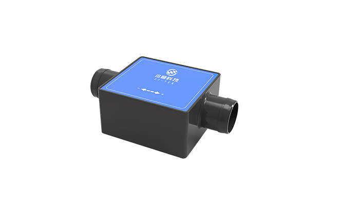
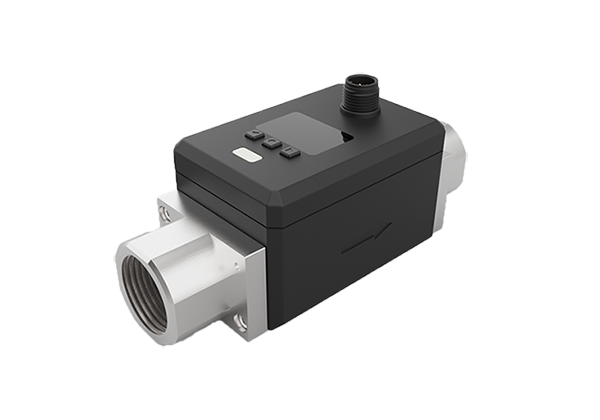
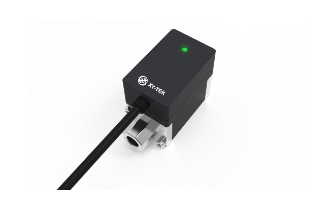
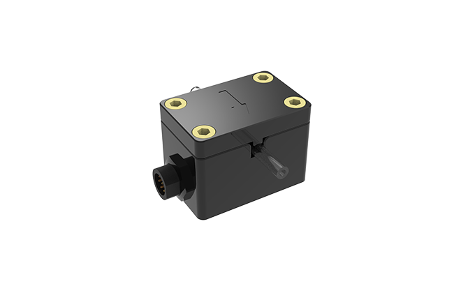
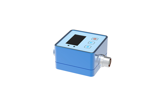
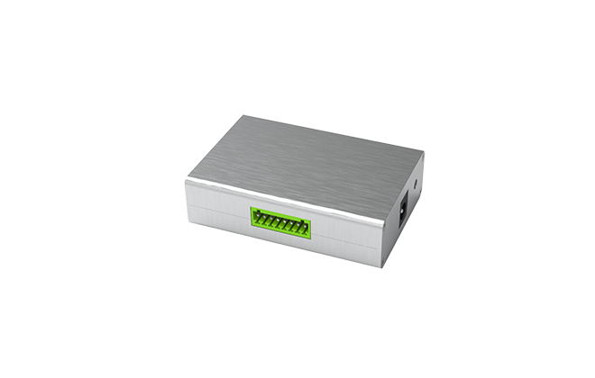
XY-TEK TPD series Ultrasonic Flow Sensor / Flow Meter
The TPD series inline ultrasonic flow sensors/flow meters feature an integrated design with a built-in circuitry, support direct flow rate measurement and intuitive flow data monitoring, ideal for industrial automation, battery manufacturing equipment, water treatment, and liquid cooling flow rate measurement.
Tubing Range DN15-DN50, support OEM and tubing size customization.
The TPD series inline ultrasonic flow sensors/flow meters can be integrated into the existing fluid systems through internationally standardized tubing fittings, with an accuracy of up to ±2%.
TPD series inline ultrasonic flow sensors/flow meters consist of straight tubing with no moving parts and dead spots, making it resistant to wear and scaliness, easy to clean, and with minimal pressure loss.
Compared to clamp-on ultrasonic flow sensors/flow meters, the TPD series flow sensor/flow meters calibration does not depend on the tubing material and diameter, enabling immediate measurement upon integration into the system.
The TPD flow sensor/flow meters are widely used in filling and spraying applications, battery manufacturing devices, liquid cooling, industrial automation systems, and more.
Applications
Industrial Automation: Filling equipment, spraying equipment, liquid cooling systems, lubrication systems, cleaning systems, etc
Battery Manufacturing: Lithium battery slurry transfer, water cooling systems, etc
Water Treatment: Wastewater Treatment Systems


 Pre-Sale
 After-Sale